buy provigil europe
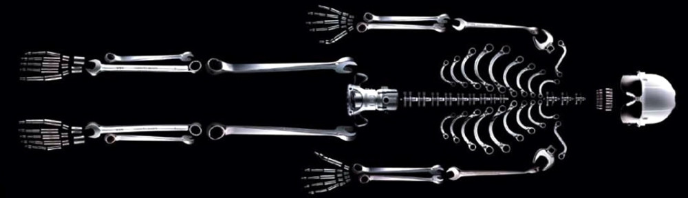
Subscripts indicate repeated monomer units, thus 09 = 000000000. Note that 79 and 89 are self-intersecting and closed.
More on the distinction between closed and open sequences later.
Fortunately, the well-known buy provigil forum file standard provides a convenient platform for producing accurate renderings of complex Lego models. So we don’t have to physically build gigantic strings of clip lights to investigate their shapes and properties.
The image above was produced using buy provigil from mexico, an open-source real-time 3D viewer for LDraw model (.ldr) files, which came bundled with a distribution of buy provigil fast shipping I downloaded some time ago. I think it probably still does.
The labels were added in Adobe Illustrator. They follow buy provigil from uk for indicating the relationship of a child monomer to its parent. Following the conventions of chemical empirical formulae, the subscripts indicate repeated monomer units, so that, for example 09 = 000000000. buy provigil fast Remember that the starting monomer is never included in the notation string, so even though these are 10-mers, only 9 digits are required to describe them.
The .ldr files themselves were produced using a spreadsheet, as an exercise to understand the file format and the mathematics for calculating the position and rotation of a child monomer from those of its parent. A sample spreadsheet can be viewed buy provigil online from canada, and downloaded in OpenOffice format buy provigil france.
In point of fact, this spreadsheet can be used to iterate any “bond” between two Lego elements indefinitely. For example, here’s a spiral made by stacking two elements 3822 (“Door 1 x 2 x 3 Left”), rotated 22.5° relative to each other, about the stud, and then iterating 19 more elements using the spreadsheet:
where can i buy provigil forum
The remainder of this article will describe how the spreadsheet works.
Here’s an example .ldr file for the 59 model:
0 555555555
0 Name: 555555555.ldr
0 Author: MLCad
0 Unofficial Model
0 ROTATION CENTER 0 0 0 1 "Custom"
0 ROTATION CONFIG 0 0
1 7 0 0 0 1 0 0 0 1 0 0 0 1 4081B.DAT
1 14 -12 2 -20 0 1 0 -1 0 0 0 0 1 4081B.DAT
1 14 -10 14 -40 -1 0 0 0 -1 0 0 0 1 4081B.DAT
1 14 2 12 -60 0 -1 0 1 0 0 0 0 1 4081B.DAT
1 14 0 0 -80 1 0 0 0 1 0 0 0 1 4081B.DAT
1 14 -12 2 -100 0 1 0 -1 0 0 0 0 1 4081B.DAT
1 14 -10 14 -120 -1 0 0 0 -1 0 0 0 1 4081B.DAT
1 14 2 12 -140 0 -1 0 1 0 0 0 0 1 4081B.DAT
1 14 0 0 -160 1 0 0 0 1 0 0 0 1 4081B.DAT
1 14 -12 2 -180 0 1 0 -1 0 0 0 0 1 4081B.DAT
0
Per buy provigil generic, lines numbered 0 are comments or META commands, and can be ignored for illustrative purposes. Lines numbered 1 indicate the color, position, and rotation of a particular sub-file, in this case 4081B.DAT, which is the “Type 2” clip light part model. Simplifying further, let’s consider only the first two monomers in the chain:
1 7 0 0 0 1 0 0 0 1 0 0 0 1 4081B.DAT
1 14 -12 2 -20 0 1 0 -1 0 0 0 0 1 4081B.DAT
The second number on each line indicates the part’s color code. Per my convention, the starting monomer is always colored gray (7), and a child monomer in a “5” bond with its parent is always colored yellow (14). Stripping out the line numbers and color codes, and adding some spaces so everything lines up purty, gives:
  0   0   0  1  0  0  0  1  0  0  0  1  4081B.DAT
-12   2 -20  0  1  0 -1  0  0  0  0  1  4081B.DAT
Finally, since the part file is always going to be the same (for now), we can strip those off the ends:
  0   0   0  1  0  0  0  1  0  0  0  1
-12   2 -20  0  1  0 -1  0  0  0  0  1
Now we’re down to the heart of the matter. The first three numbers on each line are an ordered triple indicating the part’s x, y, z position in space. The remaining nine are the columns of a 3×3 matrix that describes its rotation.
The starting monomer is set at the origin (0, 0, 0), and its rotation matrix to the 3×3 identity matrix:
![\[ \left| \begin{array}{ccc} 1 & 0 & 0 \\ 0 & 1 & 0 \\ 0 & 0 & 1 \end{array} \right|\]](http://www.smragan.com/wp-content/ql-cache/quicklatex.com-b4770bc10275831616f95745a573ec59_l3.png "Rendered by QuickLaTeX.com")
In MLCad, this can be done by opening a new model, inserting a part, and then right-clicking on it and selecting “Enter Pos.+Rot….” The first child monomer is then “manually” attached to the starting monomer, in the correct position and rotation, using MLCad’s graphical interface. Its position and rotation can then be read out of the saved .ldr file or the GUI dialog.
Determining the position of third and subsequent monomers in the chain, based on the first two elements, requires calculating the x, y, z position and the rotation matrix. If the starting element is at 0, 0, 0 and has the identity rotation matrix, then the x, y, z position of the second monomer can be thought of as the characteristic displacement of the iteration, and the rotation matrix of the second monomer can be described as the characteristic rotation of the iteration.
To calculate the position x’, y’ ,z’ of subsequent monomers, we apply the characteristic displacement and rotation values for the iteration to the x, y, z position of the parent monomer. Put differently, no matter how many links down the chain we may be, we will always use the position and rotation values of the second monomer in the chain to determine the position of any child monomer. And we do it with this formula
x’ = ax + by + cz + X
y’ = dx + ey + fz + Y
z’ = gx + hy + iz + Z
where X, Y, Z is the characteristic displacement (-12, 2, -20 in this case) and the characteristic rotation matrix is
![\[ \left| \begin{array}{ccc} a & d & g \\ b & e & h \\ c & f & i \end{array} \right| = \left| \begin{array}{ccc} 0 & -1 & 0 \\ 1 & 0 & 0 \\ 0 & 0 & 1 \end{array} \right|\]](http://www.smragan.com/wp-content/ql-cache/quicklatex.com-b27273e4313ce02509caa2e1c3554e6a_l3.png "Rendered by QuickLaTeX.com")
Plugging in all the values gives
x’ = ax + by + cz + X = -12(0) + 2(1) + (-20)(0) + (-12) = -10
y’ = dx + ey + fz + Y = -12(-1) + 2(0) + (-20)(0) + 2 = 14
z’ = gx + hy + iz + Z = -12(0) + 2(0) + (-20)(1) + (-20) = -40
which is the position of the third monomer. Again, the important thing to note is that, to determine the position of the fourth and subsequent elements, we will use exactly the same values of a, b, c, d, e, f, g, h, u, X, Y, and Z that we just used. The only values that will change are x, y, and z, which will be the x, y, and z, position values of whatever parent element we’re working with.
Determining the rotation matrix of the third and subsequent elements requires matrix multiplication. Instruction in the details of matrix multiplication is beyond the scope of this article, but there are plenty of tutorials available around the tubes. Wikipedia is usually a good place to start. Assuming you understand matrix multiplication, determining the rotation matrix of subsequent monomers is simple: all you do is multiply the parent monomer’s rotation matrix by the characteristic rotation matrix, which has the same values of a, b, c, d, e, f, g, h, and i that were used immediately above.
Next up: writing a basic PERL function that accepts position and rotation information of a parent element, as well as a single digit 0-8 indicating the bonding relationship of the child monomer, and returns correct color, position, and rotation information for the child monomer in .ldr format.